Beginner Residential Electrical Outlet Wiring Diagram Database
How To Add Outlets Easily With Surface Wiring
2. Use 14 AWG copper wire for general purpose wiring (lights and receptacles). 3. Provide over-current protection of 15 amperes for general purpose wiring (lights and receptacles). 4. Install a maximum of 12 outlets on a general purpose circuit (lights and receptacles). 5. Run cable as a loop system in continuous lengths between outlet boxes,
/wiring-electrical-receptacle-circuits-through-a-receptacle-1152787-01-2a9a43dca2d04d6597dcfb791a548ff9.jpg?strip=all)
Home Outlet Wiring Basics Wiring Flow Line
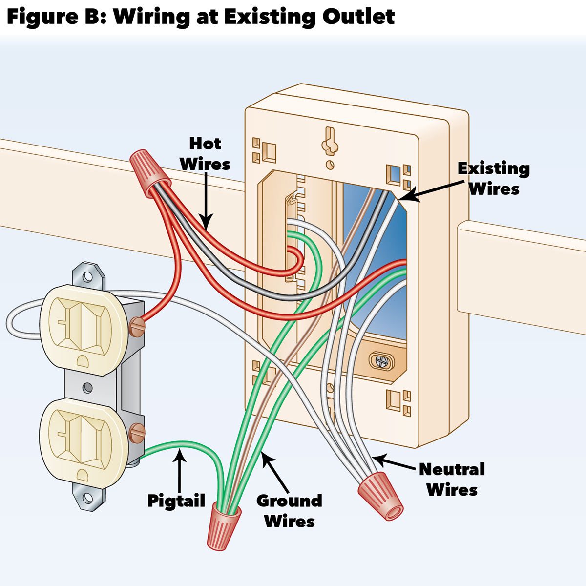
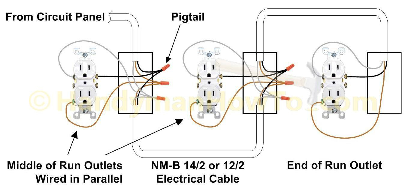
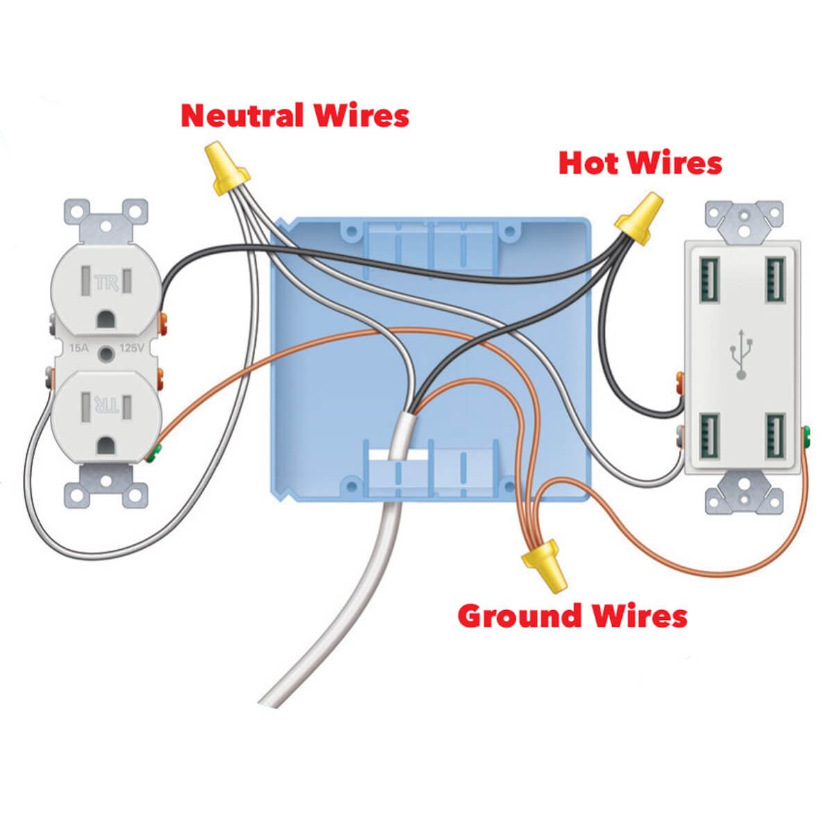
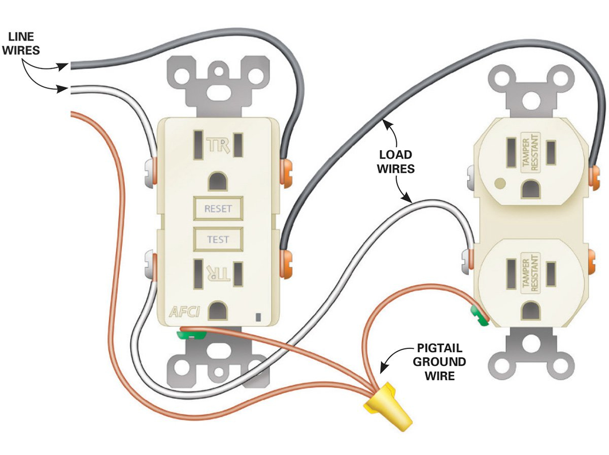
Connect the ground (bare copper) wire by combining it with the existing one (after first removing it) using a wire connector, and from there, attach a small piece to connect to the outlet's ground terminal with a green screw. However, this simple daisy-chaining method connects the two outlets in PARALLEL, not in series.
Multiple Outlet Wiring Diagram Cadician's Blog
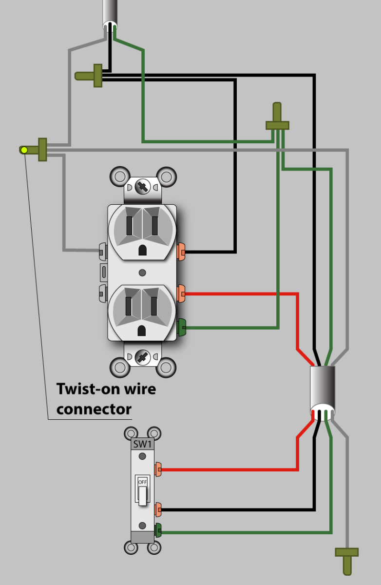
The diagram shows the power entering into the circuit at the switch box location, then sending one power line for the outlet which is hot all the time and a switched leg for the top half of the outlet being used for a table lamp or a floor fixture Instructions Switched Outlet Electrical Wiring Diagram #1

⭐Wiring Diagram 50 Amp Rv Receptacle⭐ Mixedrace couples
1 Turn Off the Electricity Open your breaker panel and turn off the power to the outlet you'll use before wiring an outlet. Use a voltage tester to check if power is off when wiring an electrical outlet. Always be sure to test the meter on a live circuit before you check to make sure the circuit that you'll be using has no power. 2
Light Switch Schematic Combo Wiring Wiring Diagram Gfci Outlet
Buying a Dimmer Switch Dimmer switches are available in many styles and configurations, including slides, knobs and touch-sensitive dimming mechanisms. However, check these key things: Capacity (how many lights it can control). The capacity will be measured in watts.
How To Wire An Electrical Outlet Under The Kitchen Sink Outlet Wiring
In this video I will show you how to wire an electrical outlet. In this receptacle wiring tutorial I go step by step in an easy to understand method. I show.

220v Welder Plug Wiring Diagram Free Wiring Diagram
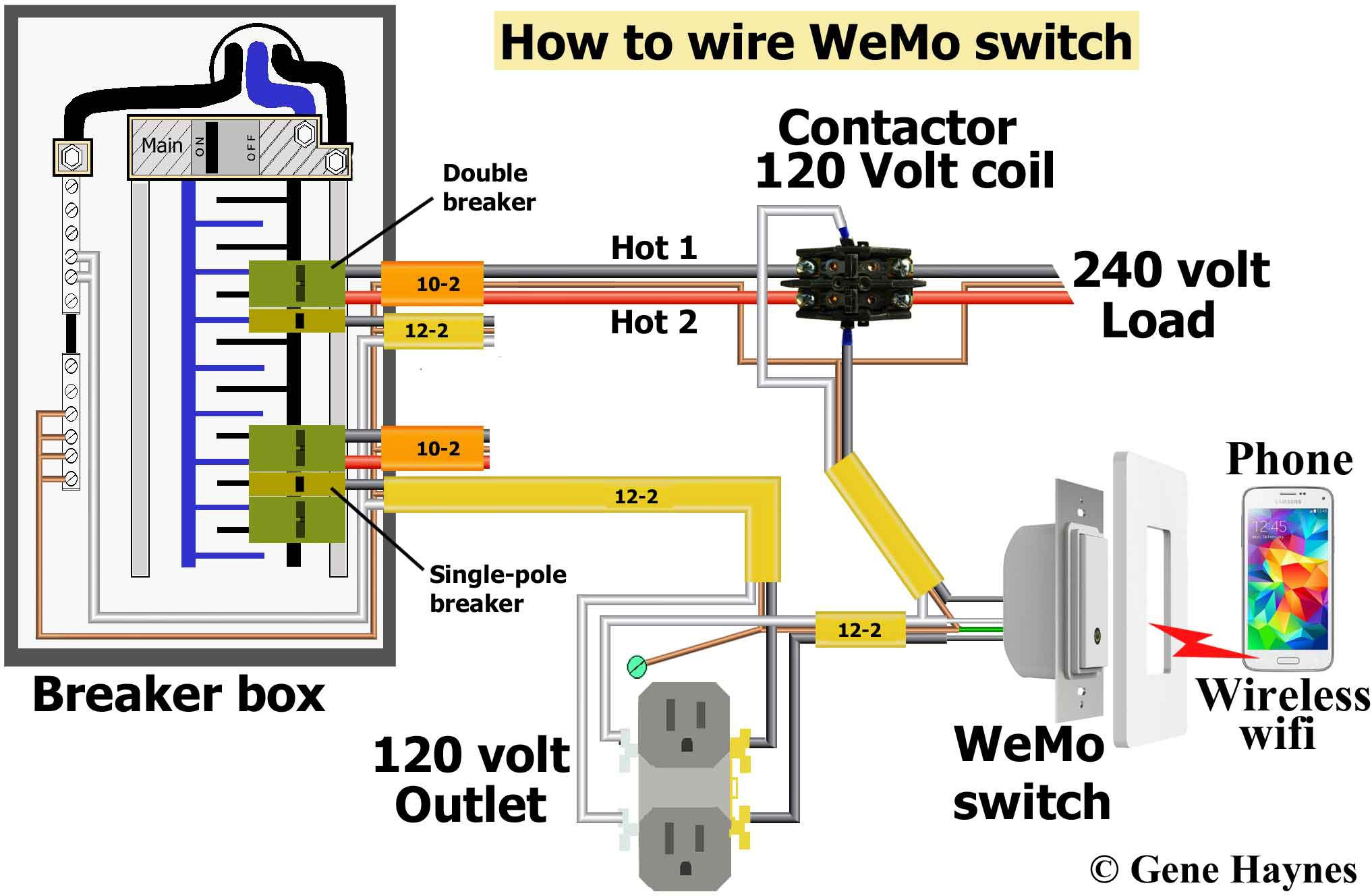
Wiring diagram of a switched electrical receptacle outlet and an unswitched electrical receptacle outlet with the power entering the switched outlet electrical box from the circuit breaker panel. The single pole switch has a neutral conductor for future electronic controls, such as a timer or a WiFi switch.

Gfci Outlet With Switch Wiring Diagram Wiring Diagram
Outlets must be no more than 3.6m apart in every open room and no more than 1.8m from a door or closet. Any wall space of 900mm or more in width requires an outlet. Outlets must be no more than 4.5m apart in a hallway. Outlets must be no more than 1.8m apart measured along the wall behind a counter top,

Leviton Switch Outlet Combination Wiring Diagram Free Wiring Diagram
Estimated Cost: $20 Wiring electrical outlets (properly called receptacles) and switches involve many of the same basic techniques. Making safe, long-lasting connections requires properly preparing the circuit wires that will connect to the device and securing each wire to the correct terminal. What You'll Need Equipment / Tools
Basic Outlet Wiring Wiring Diagrams Hubs Outlet Wiring Diagram
Introduction Eliminate those ugly and often dangerous extension cords. You can add a new outlet quickly and easily without tearing open a wall, if you already have an electrical outlet in the other side of the wall. No extra holes. No messy patching and repainting.
Beginner Residential Electrical Outlet Wiring Diagram Database
A wiring diagram is a simplified representation of the conductors (wires) and components (devices, lights, motors, switches, sensors and more) that make up an electrical circuit or electrical system.
Wiring A Light Switch And Outlet On Same Circuit Diagram Search Best
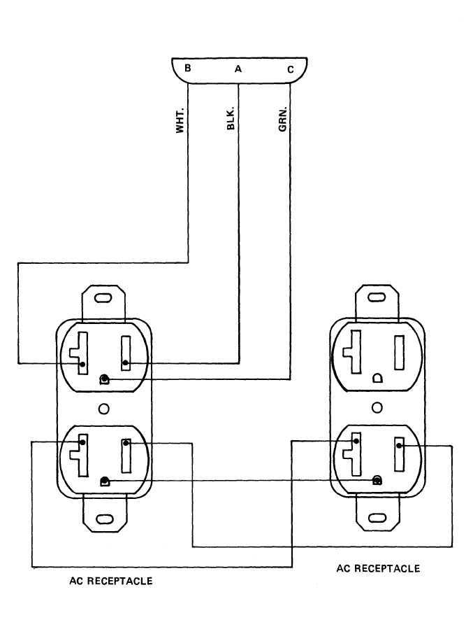
This page contains wiring diagrams for most household receptacle outlets you will encounter including: grounded and ungrounded duplex outlets, ground fault circuit interrupters (GFCI), 20amp, 30amp, and 50amp receptacles for 120 volt and 240 volt circuits. Wiring a Grounded Duplex Receptacle Outlet

Wiring Diagram Outlet How To Install And Troubleshoot Gfci How do i
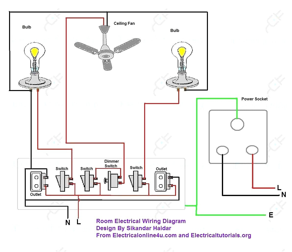
Socket Outlet Wiring Diagrams Electrical Technology 0 6 minutes read How to Wire and Install an Electrical Outlet Receptacle? Table of Contents What is an Electrical Outlet, Receptacle or Socket Outlet? Wiring Multiple Outlets in Parallel Wiring of Multiple Switched Outlets Wiring a Switch to an Outlet Wiring a 15A Outlet with Light Switch
duplex outlet wiring diagram Wiring Diagram
This page contains diagrams to add a new electrical outlet to an existing circuit. Arrangements are included to use an existing receptacle circuit or lights and switch circuits as the source for a new wall outlet. Wiring a New Outlet to Another Outlet
How To Install Electrical Outlets In The Kitchen The Family Handyman
This article and detailed wiring diagram explains the steps to wiring the common household receptacle/outlet. Included at the end of the article is a video demonstration of the proper method of an outlet. This is your standard receptacle that powers everything from your toaster to your TV.

3 Wire Outlet Diagram 3 Gang 1 Way Switch Wiring Diagram A circuit
An Electrical Receptacle/Outlet is the workhorse of a house wiring as it allows you plug in various electrical appliances and provide power. The following image shows a simple layout of all the components/parts of a regular 15A 120V Duplex Receptacle. As the name suggests, a duplex receptacle consists of two outlets to plug-in two different plugs.
